Floor Plan Above Dash

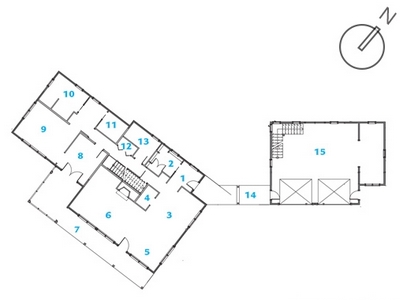
Decoding House Floor Plans
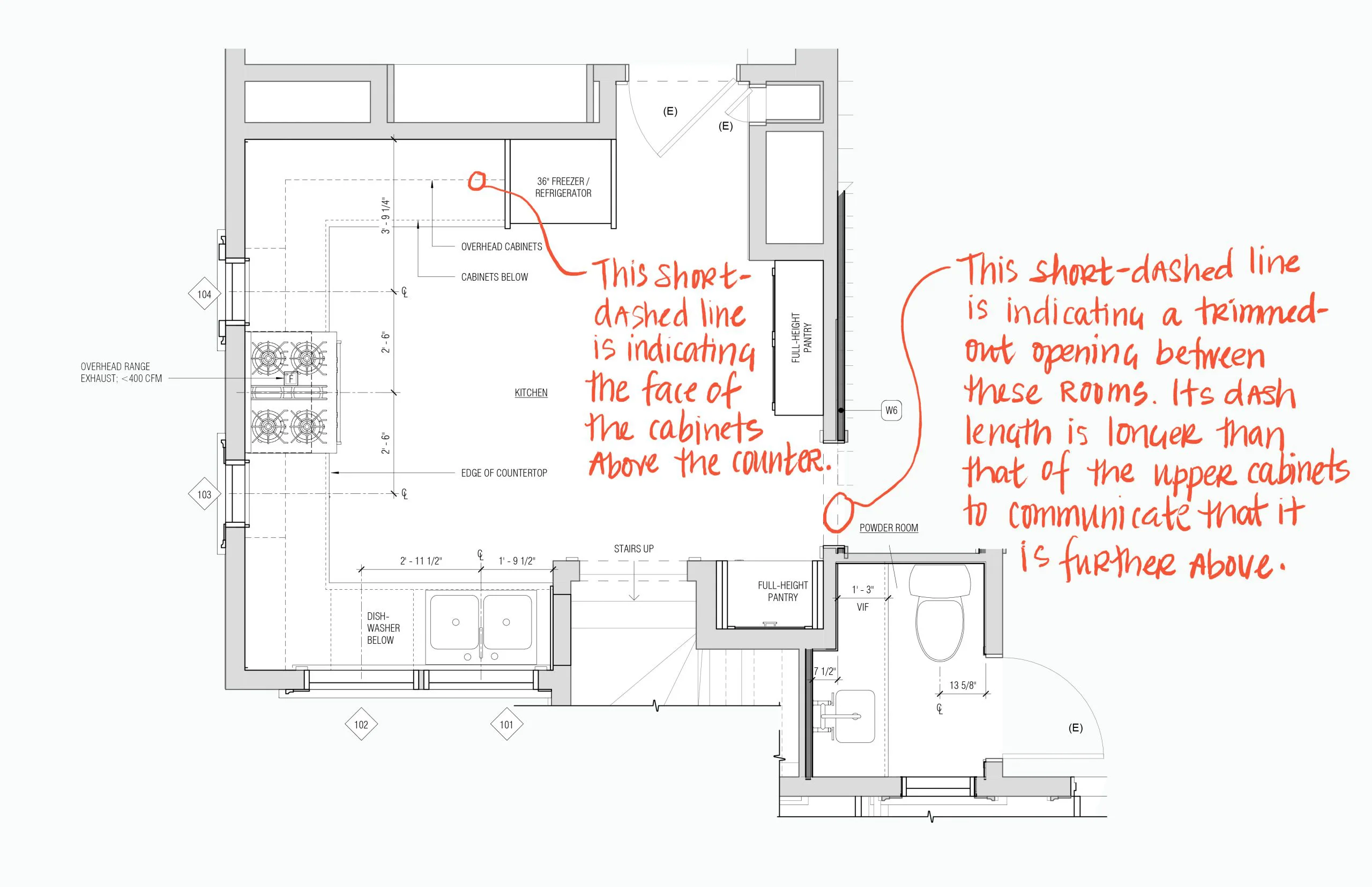
What Different Line Types In Architecture Design Drawings Mean Board Vellum

Plan 72509da Ranch With A Dash Of Craftsman Craftsman House Plans House Plans Ranch Style House Plans
Country House Floor Plans Farmhouse Inspired

Solved Roof Above How To Show Dashed Lines Autodesk Community Revit Products

Floor Plan Floor Plans Garage House How To Plan

Pocket door floor plans are drawn as thin rectangles that disappear into walls.
Floor plan above dash.

Split Entry Split Foyer Bi Level Raised Rambler Raised Ranch Home And Interior Design Ideas Split Foyer Split Entry Split Level Remodel

70 Reference Of Floor Plan Interior Drawing In 2020 House Layout Plans Building Plans House Floor Plan Layout

7 Tiny Homes Floor Plans That Make Great Bachelor Or Bachelorette Pads Carriage House Plans Garage House Plans Craftsman Style House Plans

Plan 69395am Two Bedroom Guest Suite Over 3 Car Plan In 2020 Guest Suite Floor Plan Carriage House Plans Garage Apartment Plans
Source : pinterest.com
